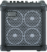
Taking apart the Micro-Cube might be the most difficult part! The metal enclosure which houses the electronics has adhesive tape holding it in place on the corners - great care and patience must be taken the disassembly. For each of these pictures, you can get a super close-up, high resolution view by double-clicking on the photo.
STEP 1: Remove the Screws Remove the 6 screws on the back and the two screws on the top. These are the only screws holding the amp in place. I also removed the strap and screws to make it less cluttered. Remove the 6 screws on the back and the two screws on the top. These are the only screws holding the amp in place. I also removed the strap and screws to make it less cluttered.Make sure to save all the screws! Once you have the screws out, you can remove the plastic top from the battery compartment. Then, you can poke your finger inside and pull the back plate out a bit to loosen it. You will notice that it feels like the upper corner is locked down, and this is the adhesive tape fighting back at you. | |
STEP 2: Loosen the Adhesive at the Top  I stuck my screwdriver in the top holes and gently pushed down on the top part of the amp, which extends up under the top of the wood enclosure. I stuck my screwdriver in the top holes and gently pushed down on the top part of the amp, which extends up under the top of the wood enclosure.Alternate back and forth between the two screw-holes until you get the metal top to break away from the enclosure top. Do not push to hard with the screwdriver or you will bend the top plate. After you get it loosened, move to the sides. | |
STEP 3: Loosen the adhesive on the Corners  With a putty knife or slender screwdriver, break the adhesive tape seal on the left and right corners of the amp. With a putty knife or slender screwdriver, break the adhesive tape seal on the left and right corners of the amp.There are two spots on each side where the adhesive is: the upper and side of each corner. This is the most difficult part and requires gingerly finessing the joint loose. By alternating with the finger-in-battery-compartment, the top screw holes, and the corners, you can slowly and eventually break the metal enclosure away from the outer wood enclosure. | |
STEP 4: Remove the Amp  Once you have broken the seal, you can pull the amp straight out. There will be four speaker wires that follow along so be careful and watch for the cables. Once you have broken the seal, you can pull the amp straight out. There will be four speaker wires that follow along so be careful and watch for the cables.When you get the amp free from the cabinet, there will be just enough slack in the speaker wires to lay the amp on its side, or upside down behind the speaker enclosure. | |
STEP 5: Disconnect the Speakers  The four speaker wires have pull-release connectors. Write down the colors and order of connections. For mine, the left pair of speakers used Brown/Light Brown wires and the right pair used Red/Black. The four speaker wires have pull-release connectors. Write down the colors and order of connections. For mine, the left pair of speakers used Brown/Light Brown wires and the right pair used Red/Black.Once you disconnect the speaker wires, the amp will be completely free of the enclosure so you can easily work on the guts of the modifications. | |
 Here's the amp and enclosure just before separating them. After separating them and while the circuit boards are firmly in place, you can drill out the holes for the speaker switch and/or the 1/4" jack. You don't want to do this after you have disconnected and separated the circuit boards. Here's the amp and enclosure just before separating them. After separating them and while the circuit boards are firmly in place, you can drill out the holes for the speaker switch and/or the 1/4" jack. You don't want to do this after you have disconnected and separated the circuit boards. | |
STEP 6: Drill and Mount the Switch and Jack  Drill out and mount one SPST Toggle Switch for the speaker mod, and one 1/4" Stereo jack for the foot switch. Note the locations of the components on the lower portion of the plate. Drill out and mount one SPST Toggle Switch for the speaker mod, and one 1/4" Stereo jack for the foot switch. Note the locations of the components on the lower portion of the plate.These jacks are located down here because there is a wood support bar across the upper part of the back - keep this in mind when you are choosing a place for mounding the switch and/or jack! If you choose the wrong location, the backside of the switch or jack will be hitting a part of the wood enclosure. | |
STEP 7: Removing the Circuit Boards  The circuit boards are connected to the rear of the amp via 2 small screws, one under the DC Power Supply jack, and the other just to the left of the Foot Switch jack. The circuit boards are connected to the rear of the amp via 2 small screws, one under the DC Power Supply jack, and the other just to the left of the Foot Switch jack.Remove these screws and set aside. If you aren't properly grounded at your workbench, now would be the time to get the anti-static strap out. After you remove these screws, the circuit boards will still require more prepping to get them apart. | |
STEP 8: Remove the Jack Nuts  Remove the three plastic nuts that hold the three 1/4" Jacks in place. You will be pulling the circuit board stack away from the back plate. Remove the three plastic nuts that hold the three 1/4" Jacks in place. You will be pulling the circuit board stack away from the back plate. | |
STEP 9: Disconnecting the Circuit Boards  There are several wire connectors that need to be disconnected to separate the two circuit boards. These include 2 multi-pin connectors on the front. These are very important and fragile so be very careful here. They connect the two boards together electronically. There are several wire connectors that need to be disconnected to separate the two circuit boards. These include 2 multi-pin connectors on the front. These are very important and fragile so be very careful here. They connect the two boards together electronically.Remove the 3 standoff screws that connect the two boards together. Finally, cut the wire tie strain relief on the small vertical board on the right of the diagram to free up the connector wire. At this point, you can now pull the pair of boards out and away from the backplate - take care because the vertical circuit board on the right needs to remain unharmed during this operation. You will need to rock the boards back and forth until the plastic 1/4" jacks come out of their holes. Also, you will need to pull the speaker wires out of the plastic strain relief connector which is glued to the metal back plate. The board on top is the CPU/Power Supply board, while the one below is the Input board, with the controllers and switches. | |